Links
Infiniti G37 Links
Sites of Interest
Recent Discussions
- Error: The URL provided does not contain data in the expected format.
- Error: The URL provided does not contain data in the expected format.
Of Interest
Wallpapers

BC Racing's Infiniti G37 Coilover Installation
|
NOTE: Some of the images within this writeup are pulled from the Tein H-Tech installation tutorial and some are from this installation process, thus, in some of the images the replaced springs will be black and in others gold. It's irrelevant which ones are shown as they are simply being removed. |
||
|
Tools needed: Car jack, jack stands, impact gun (preferred), 12mm wrench, 14mm wrench, 17mm wrench, 19mm wrench, 12-19mm sockets, rubber mallet, tape measure |
||
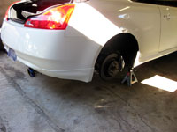 |
Step 1. Starting at the rear, jack up the car and properly support the weight of the rear on a pair of jack stands. Remove both
rear wheels. Use the rear differential as the jack point.
Yes, it is possible to do one side at a time but much easier adjusting the rear at the same time. |
|
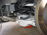 |
Step 2. The rear springs sit in a basket designed into the rear lower control arm. The control arm is attached to the main suspension
member by one 17mm bolt at the hub/axle assembly. With the vehicle on jack stands, use the jack to support the lower control arm. Remove the bolt that attaches the control arm to the
axle/hub lower mount. At this point you can lower the jack to drop the control arm. If the control arm does not lower enough or easily enough to get the spring out you can loosen the bolt where the
control arm attaches to the main suspension member. Once down enough you can pull the factory spring out. |
|
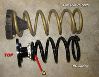 |
Step 3: First Pass Rear. The image to the left shows the new BC coil (black) and the Tein H-Tech coil (gold). You will not use the factory rubber "upper seal" (cone shaped rubber piece on top of the factory coils) when installing coilovers but you will reuse the lower bushing which is keyed to both the spring and the mounting location within the lower control arm bucket.
For the G37 the BC rear springs come with a top perch/adjustment collar, adjustment rings and mounting perch. To adjust rear height you adjust how high or low the lower mounting perch is adjusted on the collar. If you want the vehicle as low as possible you start with the lower mounting perch adjusted all the way up to the top perch. To start with the vehicle as high as possible you do the exact opposite and have the lower perch as far down the collar as possible. We started with the later configuration and the lower perch almost all the way down. Install the spring with the perch on top and install the rear adjustable shock as seen via the next step. Use the jack to raise the bucket again and reattach the lower control arm with the bolt removed from step 1. |
|
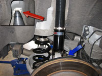 |
Step 4: Remove/Install Rear Shock. Remove the two 12mm nuts that support the top of the strut as indicated via the red arrow. Remove the 17mm bolt that holds the bottom of the
strut as indicated via the blue arrow. Set the old aside and install the new shock in reverse order. Make sure the top adjustment knobs are pointing outward for easy access. For now, leave the shocks as they are.
You may want to set the initial shocks firmness at this time. The BC system has 30-way adjustments via the knob on the top of the front struts and front side of the rear shock. I started right in the middle at "15". NOTE: Prior G37 BC coilover kits had the rear adjustment knob on the top just like the front struts. BC sold a pair of extenders for this setup which allowed a adjustment knob on a cable to be run into the trunk area for easy adjustment. G37 owners had issue with having to drill a hole in the car to run the extenders, thus, BC has redesigned the kit such that the adjuster is now on the top side of the rear shock. Extenders no longer are required nor do they fit the current setup. To adjust the rear you need to reach into the well to the top of the shock which will usually require the tire to be removed. |
|
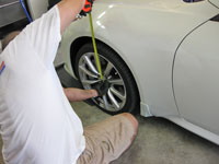 |
Step 5: Rear Height Adjustments. As noted in step 3 the rear perch was extended to maximum for the first pass. When lowering the car the rear was as high as it could go with this suspension. Before taking measurements, and with the car on the ground, we made sure the vehicle was settled by moving forward a couple feet and jabbing the brakes, then going into reverse and doing the same. This ensures there is no binding and the suspension is relatively settled. When measuring and adjusting height we used the center of the hub and measured to the fender lip, as seen via the image to the left. After settling the suspension with the roll/brake method we took a measurement. The first setting was quite high so we chose to adjust the rear height.
There is two ways to do this. You can use the supplied spanner wrenches to adjust the height manually by loosening the top lock ring and turning the lower ring Left to Right, which can take a while in confined spaces. Or you can jack up the car again and follow step 1 above to remove the spring assembly from the control arm. We did the later when performing large changes and the prior for fine tuning. With each test we rolled the car forward/backward and hit the brakes to settle. The final result had the lower perch adjusted with approximately 1/2" of collar threads showing below the lower perch mount. This set the rear center hub to fender lip at 13.75", at rest, which eventually settled to 13.5". As a comparison, the prior Tein H-Techs had a static height of 13" front and rear based on this measurement. |
|
 |
Step 6: Rear Shock Adjustments. Proper adjustment for the shocks come after setting your height. Once you have measured and verified height is set properly via step 5 you will need to set the proper preload on the coils while adjusting the shocks.
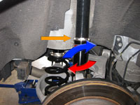
Jack the rear up and place the car on jack stands. You can also perform this task one side at a time but will need two jacks if you do it this way. After the car is raised and wheel(s) removed, use the jack to support the lower spring arm and remove the shocks lower 17mm bolt to free it from the spring arm. Use the spanner wrenches to loosen the two lower locking rings (see orange arrow). Lower the jack to allow the spring arm to hang. Springs will be loose at this point in their basket. To set preload and shocks, jack the spring arm back up until the springs themselves are no longer loose in their mounting basket. BC requires 10mm of preload so once the springs are no longer loose you should jack the spring arm up and additonal 10mm (or .4") to set preload. Once complete, adjust the shocks to the proper new height until they mate back up with their mounting location. Reinstall the 17mm bolt/nut on the shocks lower mount. Use the spanner wrenches to properly tighten the lower locking rings. Note: To lower the height of the shock you will then turn the threaded tube from right to left (red arrow). To raise the height you turn the threaded tube from left to right (blue arrow). |
|
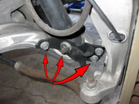 |
Step 7. Safely raise the front and remove wheels. Start by removing the 4 bolts as shown in the picture to the left. You will have a 19mm main nut and three
14mm bolts. The back 14mm bolt can be removed with an impact wrench as can the 19mm main nut. The two inner 14mm bolts will have to be removed with a wrench. Start with the lower
bolt first and do the upper bolt last. The 14mm bolts have at least 1.5" of threads so it will take a while to get them out so a ratcheting wrench would be useful.
It is also advised to remove the front connecting rod bolt to allow removal of the support bolt that goes through the lower control arm, the lower strut mount, and ends in the 19mm nut just removed. This is to allow reinstallation to be easier. |
|
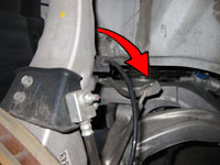 |
Step 8. There is a 12mm nut on the rear section of the strut which mounts the brake line to the strut and you cannot remove the strut with the brake line attached. I used an impact gun to remove this nut as it would be less stressful than trying to bust the nut off with a wrench. There are additional lines using the strut as a mount point and these should be removed at this time. Here is an additional image showing the location of the 12mm bolt on the strut. | |
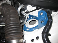 |
Step 9. Inside the engine bay there are three nuts holding the top of the strut in place. Remove these three nuts and the strut
will be ready to removal. For additional information on removing the bolts on the strut tower, view the Front Strut Tower Brace how-to.
It should be noted that the blue bracket in the left image is not on a G37 but is the mounting bracket from a GTspec FSTB.
To remove the strut you will have to be careful since the brake line actually goes around it. Angle the bottom out and start twisting while sliding it out. |
|
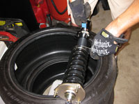 |
Step 10. When you receive your struts they should be pre-loaded at the factory. Take this time to ensure the lock ring is tight by using the supplied spanner wrenches to tighten the top ring as shown via the image to the left. | |
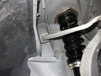 |
Step 11. Slide the new strut in place and attach using the three nuts removed from the prior step. When installing the strut remember to thread it through the brake lines as it was before. | |
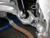 |
Step 12. To mount the strut to the lower control arm you may need to use the floor jack to adjust the lower control arm. Once aligned, slide the mounting bolt in place. If you removed the connecting rod bolt, reattach at this time. Put the plate back in place on the lower control arm, reinstall the 19mm nut and the three 14mm bolts. | |
 |
Step 13. Time for measurements. Put the wheels back on the car and lower it back down. Move it forward and back, with braking, to settle the suspension similar to step 5 above. Step back and determine what you need to do from a height perspective. In my case I knew I wanted to be in the 13.5" range from center of the hub to the fender lip and I was appx 1.5" too high as it sat, thus, I needed to adjust the suspension down in front by that same 1.5". | |
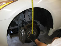 |
Step 14. Raise the vehicle and remove the wheels again. Take a measurement to determine the hanging height of the axle. We used the bottom of the hub and measured to the bottom of the fender. This measurement helpful in determining how much you have changed the height when adjusting the front struts. | |
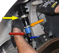 |
Step 15. As it sets the strut has a locking ring for the bottom (orange arrow) and two on top (yellow arrow). Use the smaller spanner wrench and loosen the lower
locking ring and raise it up a few inches where it will be out of the way (as seen via the image).
Lowering VehicleTo lower the vehicle we measured from the bottom of the collar (where the lower lock ring was) and put a piece of tape at the target height (blue tape bottom is the target adjustment). Using the large spanner wrench on the top-most locking ring (yellow arrow), turn the strut counter clockwise (Right to Left) until the bottom of the tape (red arrow) hits the bottom of the strut mount. Remove the tape and move the lower locking ring back into place and tighten with the small spanner wrench.Raising VehicleTo raise the vehicle you begin by putting the tape on the threads where they go into the lower strut mount (where the lower lock ring was). To raise you use the opposite top locking ring which is the lower and smaller of the two. Using the smaller spanner wrench turn the strut clockwise (Left to Right) until the tape raises the required height. Remove the tape and lock down the lower locking ring. |
|
 |
Step 16. Using the measurements from step 14, check the distance again to see if the desired height change has been met. If not, adjust the height accordingly using the above steps. | |
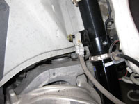 |
Step 17. When completed with height adjustments, attach the brake line to the brake mounting point on the new strut as seen via the image to the left. Tighten the nut holding the line and then tighten the mounting collar to the strut. | |
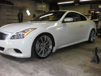 |
Step 18. Lower the car back down and resettle it. Ensure the ride height is where you want it. If not, determine what you would like to change and proceed to follow the above steps to adjust the suspension.
If the height is adequate then you are done. Drive the vehicle for a couple of weeks until everything is settled and take measurements to determine the final numbers. Adjust if needed. |
|
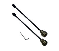 |
Rear Control Extenders Early models of the BC Racing coilovers had the adjustment knobs on top of the shock in the rear. For adjustability they had rear extenders which mounted on the knob and was fed into the trunk area via drilling a hole. As numerous customers complained about drilling a hole in their car to adjust the shocks, BC redesigned the where the adjusters are now on the side. Sadly, the rear extenders no longer work in that configuration, thus, the only way to adjust rear damping on the shock is to remove the wheel and reach up into the wheel well. Well, unless you have the car relatively high. | |
Disclaimer: The author will not be held responsible nor held liable for any damages due to these instructions. Anyone following these directions are doing so at their own risk. This Documentation may not be distributed without the authors consent. |
||


