Links
Infiniti G37 Links
Sites of Interest
Recent Discussions
- Error: The URL provided does not contain data in the expected format.
- Error: The URL provided does not contain data in the expected format.
Of Interest
Wallpapers

Tein H-Tech Spring Installation
 |
The following directions may be utilized to help install new springs in Infiniti G37 models. In this case, a 2008 G37 coupe.
Installation time is approximately 2-4 hours dependant on issues. Overall drop is 2" front and 1.25" rear.
Special thanks to TunerzStore.com for their help in choosing the springs, technical assistance, and quick delivery. |
|
|
Tools needed: Car jack, jack stands, coil spring compressors, impact gun (preferred), 12mm wrench, 14mm wrench, 17mm wrench, 19mm wrench, 12-19mm sockets, rubber mallot |
||
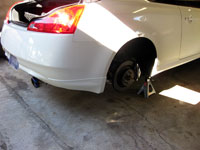 |
Step 1.Starting at the rear, jack up the car and properly support the wight of the rear on a pair of jack stands. Remove both
rear wheels. Use the rear differential as the jack point. |
|
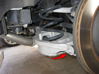 |
Step 2. The rear springs sit in a basket designed into the rear lower control arm. The control arm is attached to the main suspension
member by one bolt, one at the hub/axle assembly. With the vehicle on jack stands, use the jack to support the lower control arm. Remove the bolt that attaches the control arm to the
axle/hub lower pillow mount. At this point you can lower the jack to drop the control arm. If the control arm does not lower enough or easily enough to get the spring out you can loosen the bolt where the
control arm attaches to the main suspension member. Once down enough you can pull the factory spring out. |
|
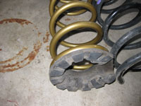 |
Step 3. While removing the springs the lower rubber bushing will come off with the factory springs while the top mount should stay in place.
The lower bushing is keyed to both the spring and the mounting location on the lower control arm (image to left shows rubber bushing on the new springs). To reinstall the spring, put the rubber
bushing back in the crontrol arm cradle and adjust according to the "key" stamped in the rubber and the control arm basket. Slide the top of the spring on the top rubber mount and then turn
it until it properly fits in the lower rubber mount. Once complete you can now start jacking the lower control arm back into place and compressing the spring. To get the lower control arm to
properly align with the axle/hub lower pillow mount you will need someone to twist the lower control arm from side to side until it is in place and the bolt hole lines up. Reinstall the bolt and tighten
it down. If you loosened the bolt where the control arm attaches to the main suspension member you can tighten that bolt up at this time. You have now replaced a rear spring. Comparison of factory spring and Tein H-Tech |
|
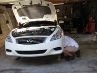 |
Step 4. To start the front you will need to jack up the car and use jack stands to support the front. Use the center brace directly below
the engine as the jack point. If the location you select flexes then you are at the wrong spot. |
|
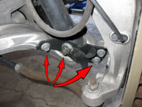 |
Step 5. Start by removing the 4 bolts as shown in the picture to the left. You will have a 19mm main nut and three
14mm bolts. The back 14mm bolt can be removed with an impact wrench as can the 19mm main nut. The two inner 14mm bolts will have to be removed with a wrench. Start with the lower
bolt first and do the upper bolt last. The 14mm bolts have at least 1.5" of threads so it will take a while to get them out so a ratcheting wrench would be useful. It is also advised to remove the front connecting rod bolt to allow removal of the support bolt that goes through the lower control arm, the lower strut mount, and ends in the 19mm nut just removed. This is to allow reinstallation to be easier. |
|
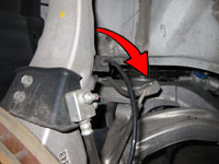 |
Step 6. There is a 12mm nut on the rear section of the strut which mounts the brake line to the strut and you cannot remove the strut with the brake line attached. I used an impact gun to remove this nut as it would be less stressful than trying to bust the nut off with a wrench. There are additional lines using the strut as a mount point and these should be removed at this time. Here is an additional image showing the location of the 12mm bolt on the strut. | |
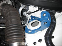 |
Step 7. Inside the engine bay there are three nuts holding the top of the strut in place. Remove these three nuts and the strut
will be ready to removal. For additional information on removing the bolts on the strut tower, view the Front Strut Tower Brace how-to.
It should be noted that the blue bracket in the left image is not on a G37 but is the mounting bracket from a GTspec FSTB.
To remove the strut you will have to be careful since the brake line actually goes around it. Angle the bottom out and start twisting while sliding it out. |
|
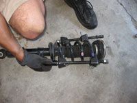 |
Step 8. Use spring compressors to take the load off the top pearch to allow removal of the shock absorber mounting bracket. Only tighten each side a bit at a time in order to keep the other side from angling in which will not allow a socket to be installed. Once compressed, use a 17mm socket to remove the top center nut. At this point you will be able to remove the top mount, bound bumper and rubber seat. The coil can now be removed. Pay close attention to the alignment of the bolts on the top perch as they are positioned on the strut. | |
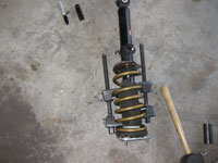 |
Step 9. Use the spring compressors again on the new springs. Once compressed, install the top mount, bound bumper and rubber seat section before sliding the springs over the strut. The strut mount is "keyed" so make sure the end of the spring is properly placed. | |
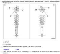 |
Step 10. CRITICAL: Prior to installing the top nut you must make sure the top mount is properly aligned. Unlike coilover installations you cannot swivel the top mount so it must be installed properly. The top mount has bolts in a triangle pattern and if it is offset improperly there is no way to readjust once the top bolt has been added. The image to the left depicts the center line of the strut which should line up with one of the top mount bolts, yes, in the picture the top mount is positioned incorrectly as the bolt is about 30 degrees or so off. Properly align the bolt and install the top nut to complete the spring installation. | |
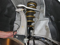 |
Step 11. Reinstall the strut starting with the strut tower mounting bolts. Don't forget to thread the strut through the brake lines.
Hold the strut in place while someone installs the strut tower mounting bolts. To mount the strut to the lower control arm you may need to use the floor jack to adjust the lower control arm. Once
aligned, slide the mounting bolt in place. If you removed the connecting rod bolt, reattach at this time.
Put the plate back in place on the lower control arm, reinstall the 19mm nut and the three 14mm bolts. Reattach the brake line with the 12mm nut. Reattach the ABS lines to their strut mounting locations......You have now completed replacing a front spring. Before putting wheels back on it is suggested to retighten all bolts to ensure they are properly tight. |
|
Disclaimer: The author will not be held responsible nor held liable for any damages due to these instructions. Anyone following these directions are doing so at their own risk. This Documentation may not be distributed without the authors consent. |
||


