Links
Infiniti G37 Links
Sites of Interest
Recent Discussions
- Re: Dynamic Cruise Control on G37?
- Re: Dynamic Cruise Control on G37?
- Re: Dynamic Cruise Control on G37?
- Re: Dynamic Cruise Control on G37?
- Re: Finndurance Motorsports G35 Endurance race car build thread
- Re: Finndurance Motorsports G35 Endurance race car build thread
- Re: Finndurance Motorsports G35 Endurance race car build thread
- Re: 2 more questions. TPMS light and aftermarket keyfob
- 2 more questions. TPMS light and aftermarket keyfob
- Re: Finndurance Motorsports G35 Endurance race car build thread
- G35 and G37 Engine, Drivetrain & Tuning • Re: U1000/U1001 after complete drivetrain and wiring swap
- G35 and G37 Engine, Drivetrain & Tuning • Re: U1000/U1001 after complete drivetrain and wiring swap
- G35 and G37 Engine, Drivetrain & Tuning • Re: U1000/U1001 after complete drivetrain and wiring swap
- G35 and G37 Engine, Drivetrain & Tuning • Re: U1000/U1001 after complete drivetrain and wiring swap
- G35 and G37 Engine, Drivetrain & Tuning • Re: U1000/U1001 after complete drivetrain and wiring swap
- G35 and G37 Engine, Drivetrain & Tuning • Re: U1000/U1001 after complete drivetrain and wiring swap
- G35 and G37 Engine, Drivetrain & Tuning • Re: U1000/U1001 after complete drivetrain and wiring swap
- G35 and G37 Engine, Drivetrain & Tuning • Re: U1000/U1001 after complete drivetrain and wiring swap
- G35 and G37 Engine, Drivetrain & Tuning • Re: U1000/U1001 after complete drivetrain and wiring swap
- G35 and G37 Engine, Drivetrain & Tuning • Re: U1000/U1001 after complete drivetrain and wiring swap
Of Interest
Wallpapers

Infiniti G37 R2C intake installation instructions
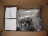 |
The R2C intake system came nicely packaged and protected. Everything was individually wrapped and neatly packed. Before starting any installation you should lay out all the parts to ensure they are in the box. In this case the intakes were missing the couplers and the installation was pushed until R2C could send another set. | |
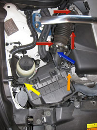 |
Step 1: Factory Intake The left image depicts the factory intake (in this case the passenger side) system. Removal of the
factory intake system is as follows:
The screw-style clamps are attached to the factory parts and won't fall off. The compression-style clamp for the crankcase vent is not and will be reused, use the pliars to remove and set it aside. Once all steps are complete, disconnect the intake tube and remove. Pull the intake box up and remove the unit. On each side there is a junction for the crankcase pipe, these should be removed as well. |
|
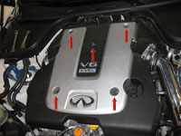 |
Step 2. When I started the install I tried working around the engine cover. Hey, why remove something when it's not necessary? For the time required to remove a couple of bolts, it's worth it. Even in my case where I needed to remove the aftermarket strut tower brace it was still worth it. Remove the 5ea 10mm bolts and set the engine cover to the side.
At this point you have both intakes removed or you have at least one side removed. |
|
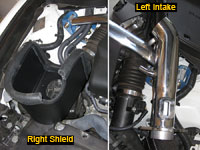 |
Intake Layout Before putting the intakes together you should understand this is not a universal kit in that there are left and right intake tubes and airbox shields. The image to the left depicts the differences. The right side (passenger side) airbox has a cut out for the radiator pipe. The intake tubes will have the MAF sensor mounting location on the top the the crankcase vent tube will be towards the motor (left side/drivers side depicted). Make sure you put the correct tube with the proper sheild when putting the intake system together. |
|
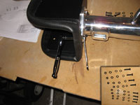 |
Step 3. Time to attach the intake tubes to the airboxes. Each tube has four 8mm bolts. When installing each bolt you will have the bolt, a lock washer, a washer, intake tube/airbox, washer, 8mm nut. I used a 1/4" ratchet, deep-well 8mm socket, and a 8mm wrench to tighten them down. It should be noted that the rubber seal at the top of the airbox will be in the way and need to be moved about in order to flush-install the pipe. |
|
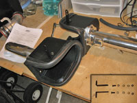 |
Step 4. Install the two airbox mounting brackets as seen in the left image. Similar to the airbox setup you have the 10mm bolt, lock washer, and washer on one side and a washer and 10mm bolt on the other. I installed with the bolt sticking out from the airbox and finger-tightened the bolts. |
|
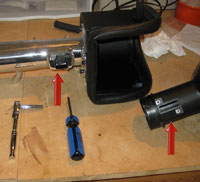 |
Step 5. Time to move the MAF from the factory intake airbox to the new R2C intake tubes. BE VERY CAREFUL WITH THE MAF SENSOR and don't even touch the sensor itself. I made sure the MAF was installed on the proper side and facing the proper direction as seen via the image to the left (showing factory left airbox with R2C left intake tube and airbox). I simply removed one and moved it directly to it's new intake tube. The two screws that hold the MAF can be removed via phillips screwdriver or 7mm wrench/socket. I used a 1/4" ratchet with 7mm socket to break the screws loose and then used the screwdriver to remove them. Installation was in reverse order. Do both sides and don't over tighten. | |
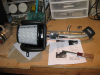 |
Step 6. Installation of the filter is a snap. Put a clamp on the filter flange and slide it over the inlet tube within the airbox. I used a 8mm nut driver with 8mm socket to tighten down the clamp instead of fumbling with a screwdriver as it's much easier. Make sure you spin the filter so the mesh screen, shown in the left image, is not showing. | |
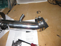 |
Step 7. In preparation for the installation I put the coupler and two clamps on the intake tube. The couplers are not that tight and the tube is easy to install so you could pre-install each coupler to the throttle body and simply put the second clamp on before installing the tube. Looking back at the installation "after the fact" I would have probably done just that. Regardless, I really had no issues with this portion of the install. | |
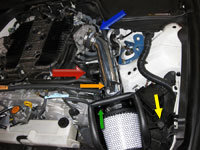 |
Step 8. Install the left (driver's side)
|
|
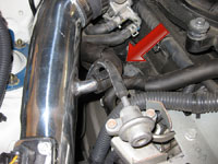 |
Step 9. Install the right (passenger's side) the same was as the prior step. BUT, there is a difference.
R2C includes a new pipe and two screw clamps to replace the factory crankcase pipe. You can install this pipe OR you can use the factory pipe. I found that I could actually flip the factory pipe and it would fit the intake almost perfectly, I validated the pipe was not setup for 1-way air passage first. I flipped the pipe and used the factory clamps as seen via the iamge to the left. |
|
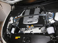 |
Step 10. Tighten down and validate all connections. Reinstall the engine cover. Enjoy!
|
|
Disclaimer: The author will not be held responsible nor held liable for any damages due to these instructions. Anyone following these directions are doing so at their own risk. This Documentation may not be distributed without the authors consent. |
||


